Introduction
For several decades, the networking industry operated in a bottom-up approach. At the bottom of the system are the fixed-function Application Specific Integrated Circuits (ASICs) or other domain-specific hardware, which enforce protocols, features, and processes available in the switch or the Network Interface Card (NIC). Programmers and operators are limited to these capabilities when building their systems. Consequently, systems have features defined by the vendors that are rigid and may not fit the network operators’ needs. P4 allows agility in the networking industry by enabling a top-down approach to the design of network applications. With this approach, the programmer or network operator can precisely describe features and how packets are processed in the packet processing pipeline. DPDK
With the Portable NIC Architecture (PNA) [1], the programmer defines the headers and corresponding parser as well as actions executed in the pipeline and the deparser. The programmer has the flexibility of defining custom headers (i.e., a header not standardized). Such capability is not available in non-programmable devices. The Data Plane Development Kit (DPDK) accelerates packet processing and enhances performance. With P4-DPDK, the programmability features of P4 and the acceleration capabilities of DPDK come together.

Figure 1: Ethernet header.
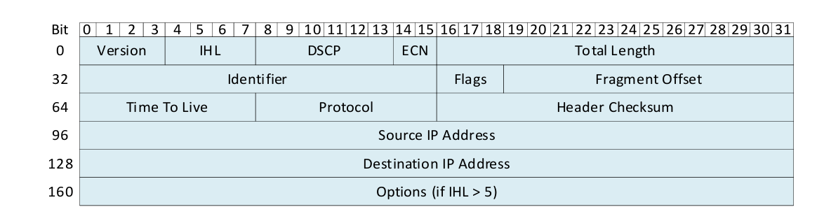
Figure 2: IPv4 header.
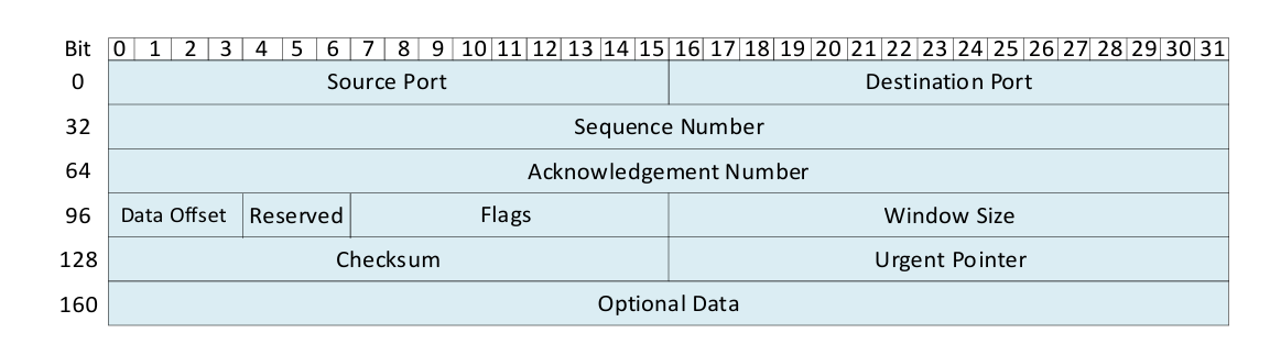
Figure 3: TCP header.
Figure 4 shows an excerpt of a P4 program where a header is defined. This is typically written at the top of the program before the parsing starts. We can see that the programmer-defined header corresponds to Ethernet (lines 11-14). The Ethernet header fields are shown in Figure 1.
The programmer also defined an IPv4 header (lines 16-29) and a TCP header (lines 31-42). The IPv4 header format is shown in Figure 2 and the TCP header is shown in Figure 3.

Figure 4: Program headers and definitions.
The code starts by including the core.p4 file (line 1) which defines some common types and variables
used in all P4 programs. For instance, the packet_in and packet_out extern types which represent
incoming and outgoing packets, respectively, are declared in core.p4 [2]. Next, the pna.p4 [3] file is
included (line 2) to define the PNA architecture and all its externs used when writing P4 programs [4].
Line 3 defines a 16-bit constant TYPE_IPV4 with the value 0x800. Similarly, line 4 creates an 8-bit
constant TYPE_TCP with the value 6. This means that these variables can be used later in the P4 program
to reference the associated values. The typedef declarations (lines 8-9) are used to assign alternative
names to types.
The program in Figure 4 defines the Ethernet header (lines 11-14). The declarations inside the header are
usually written after referring to the standard specifications of the protocol. Note that in the ethernet_t
header, the EthernetAddress is used rather than using a 48-bit field. The IPv4 header is also defined
(lines 16-29) following the standard header specification shown in Figure 2. Note that in the ipv4_t header,
the IP4Address is used rather than using a 32-bit field. Similarly, the TCP header is defined (lines 31-42)
following the standard header specification shown in Figure 3. Lines 44 - 45 show how to declare user-defined
metadata, which is passed from one block to another as the packet propagates through the architecture. For
simplicity, this program does not require any user metadata. Finally, the headers struct (lines 47-50) that
will be used in the program are defined. The headers are customized depending on how the programmer wants
the packets to be parsed.
Programmable parser
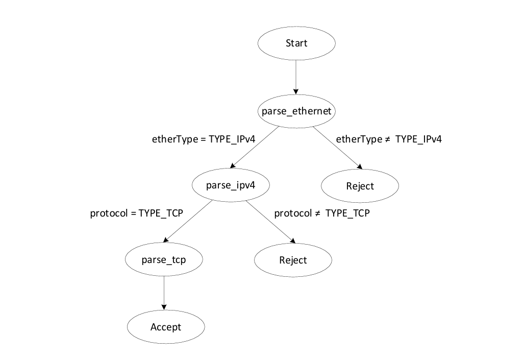
The programmable parser permits the programmer to describe how the packets will be processed. The parser de-encapsulates the headers, converting the original packet into a parsed representation of the packet. The parser can be represented as a state machine without cycles (direct acyclic graph), with one initial state (start) and two final states (accept or reject).
(a)

(b)
Figure 5. Example of a parser. (a) Graphical representation of the parser. (b) In P4, the parser always
starts with the initial state called start. First, we transition unconditionally to parse_ethernet.
Then, we can create some conditions to direct the parser. Finally, when we transition to the accept state,
the packet is moved to the control block of the pipeline. A packet that reaches the reject state will be
dropped.
Figure 5a shows the graphical representation of the parser and Figure 5b its corresponding P4 code.
Note that the packet is an instance of the packet_in extern and is passed as a parameter to the parser.
The extract method associated with the packet extracts N bits, where N is the total number of bits defined
in the corresponding header (for example, 112 bits for Ethernet). Afterward, the etherType field of the
Ethernet header is examined using the select statement, and the program branches to the parse_ipv4 state
if the etherType field corresponds to IPv4. The state transitions to the reject if it is not an IPv4 header,
as shown in the figure above (Line 15). In the parse_ipv4 state, the protocol field of the IPv4 header is
examined using the select statement, and the program branches to the parse_tcp state if the protocol field
corresponds to TCP. The state transitions to the reject if it is not a TCP header, as shown in the figure
above (Line 23). Finally, in the parse_tcp state, the TCP header is extracted, and the program unconditionally
transitions to the accept state.